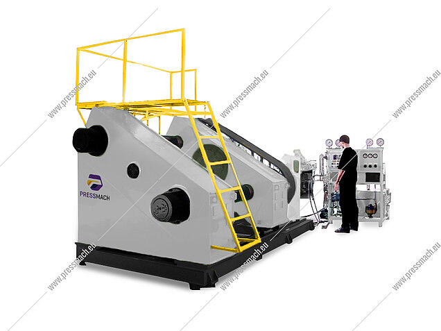
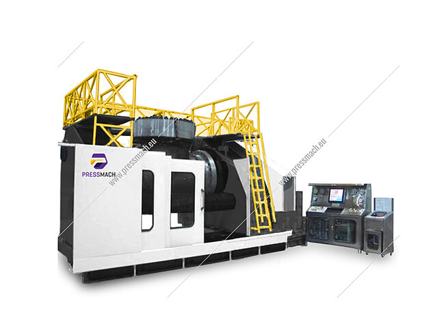
Horizontal Valve Test Benches
The Pressmach Horizontal Valve Test Benches are available up to 3000 tons and the valve size is ranging up to 42". Our test machines are robust and come with a wide array of technologies that make pressure testing of your valves easier with accurate results and reliable performance. Horizontal means that test fluid flow direction is horizontal and valve stem direction is vertical.
SPECIFICATIONS DETAILS
Parameter
| Model | Unit | EPHH-1000TB | EPHH-1500TB |
| Nominal capacity | tf | 1000 | 1500 |
| Pressure | Mpa | 65 | 40 |
| Distance between columns | mm | 1450 | 1525 |
| Max. distance between faces | mm | 2350 | 2700 |
| Min. distance between faces | mm | 500 | 500 |
| Centre height | mm | 1550 | 1680 |
Technical Specifications
HYDRAULIC POWER PACK:
The hydraulic power pack is responsible for movement of the moving beam, support cylinder, carriage and generating the clamping pressure. The hydraulic power pack is designed to conserve power. It goes to idle mode whenever it is not being used.
AIR HYDRO PANEL:
The Air Hydro Panel is fabricated from stainless steel with a satin finish. This panel houses the pressurization system, electrical and electronic control systems and also serves as the operator panel. The panel is ergonomically designed for comfortable operation of all valves and electrical push buttons.
CLAMPING AND ACTUATION:
- Clamping - Multiple Hydraulic Cylinders.
- Beam Traverse - Through rotary nut actuated by hydraulics.
- Bottom Valve Support - Hydraulic Cylinder
- Bottom Support traverse - Hydraulic Cylinder
- All auto hydro valves - Pneumatic actuated
- All auto hydraulic valves - Solenoid actuated
INSTRUMENTS:
The test machine uses precision calibrated instruments for both analogue and digital measurement. Details are as found below. Analogue Pressure Gauges Digital Pressure Transmitters Digital Bubble Counter
PROPORTIONAL CLAMPING
This machine uses proportional clamping with the help of feedback circuits to clamp the valves. This is of particular importance in case of testing by clamping between faces where the clamping load may cause deformation on the valve seat. The system calculates the appropriate clamping force corresponding to the hydro pressure at the moment and applies accordingly thus protecting your valve by ensuring there is virtually no load acted on the valve during the testing process.
OPERATION LOADING:
The valve is loaded with a crane with valve stem in vertical position. The support cylinder can be used to position the valve. In case of bore sealing, the moving beam is moved inside until the sealing plates penetrate the valve bore completely. In case of face sealing, the moving beam is moved and kept abut with the valve. Minimal load will be exerted during this procedure. After the valve is placed in position, the Clamp button is pushed and proportional clamping is activated. Since the clamping is proportional, the clamping load exerted will only be marginally higher than the reaction force generated due to the water pressure. This load may not be sufficient enough to hold the valve in position. Hence, during face sealing, it is always recommended to secure the valve with a crane.
VACUUM:
This machine has state of the art vacuum system with an oil lubricated vacuum pump that is more efficient and powerful than ordinary pneumatic ejector type vacuum systems used in other test benches. However, this introduces some complexity in controlling and safeguarding the system. Hence the vacuum system is completely automated. Vacuuming is absolutely essential in all horizontal test benches for testing safely and getting reliable results.
FILLING:
A dedicated filling pump is provided for quick filling of the valve. Completion of filling is identified by the increase in water pressure inside the valve. As the pressure increases the vacuum pump turns off automatically. Filling, vacuuming and drain operations are carried out on the preferred side of the test bench indicated by ‘P’ which is the fixed side.
PRESSURIZING:
The Hydro pump is turned on after filling. Pressurizing can be done through the port on either side. As the hydro pressure rises, the clamping pressure also rises proportionally based on the size of the valve that is set by the user.
LEAK DETECTION (HYDRO):
After the required pressure is reached, the stations are isolated using isolation valves. The leakage can be identified using pressure drop in the gauge or in the digital reading in HMI or Computer. Alternately, for shell tests, the valve can be checked for wetting to identify leakage. For seat tests, the leakage can be visually checked through the vent port in the opposite side by the number of drops displaced.
AIR TEST:
Air seat test is done at 6-7 bar using the line pressure and this pressure can be regulated. Leak during air seat test can be quantified by the number of bubbles of air leaked. A bubbling arrangement can be connected to the vent port for this purpose. When ordered with digital bubble counter, the number of bubbles leaked is displayed in the HMI or Computer.
SAFETY
Interlock to avoid de-clamping at high pressure for personnel safety. System checks for clamping pressure continuously and prevents water pressure from rising if sufficient clamping pressure has not reached. In case of power outage, the clamping pressure is locked allowing the operator to safely release the water pressure. Safety shield for operator with shatter proof glasses laminated with Poly carbonate inner core.
ACCESSORIES:
Test bunks (sealing plates) (a) Test Bunks are designed for Flanged ends. Bunks for other types like Butt Weld / Socket Weld / Threaded End do not fall under our scope. The dimensions of the ‘O’ ring grooves are decided based on flange dimensions as described in ANSI B16.5 / ANSI B16.47. Test Bunks for other standards are available on request.
DATA LOGGING SYSTEM
The test data is logged by a custom software system. All digital data including test pressure, pressure drop, and bubble counts can be logged in the system which can either be printed as a test report or saved in the computer for future reference. The computers run on Microsoft Windows operating system. The software system is capable of generating custom reports and provides a hard copy of the report through the attached printer. All other software required for essential functioning of the system is factory fitted. Computer is attached with the test machine for control, data logging and data retrieval. The system is fitted with a Colour Inkjet Printer for test report printing. (a) Test bunks for other types of valves (Butt Weld, Socket Weld, and Threaded End) shall be supplied on request and these are not part of the standard machine.